Fuel Cells for Public Utility and Industrial Power
Although much of the interest in fuel cells is due to their efficient use of fuel, there are considerable pollution control advantages to be gained as well. Because the fuel reacts electrochemically rather than by burning in air, no nitrogen oxides are formed. For the same reason, emissions of unburned and partly burned gaseous and particulate products are essentially nil. The only moving parts in fuel batteries are fuel pumps and, perhaps, electrolyte pumps, so operation is inherently very quiet. There is relatively little thermal pollution because less energy is lost as heat.
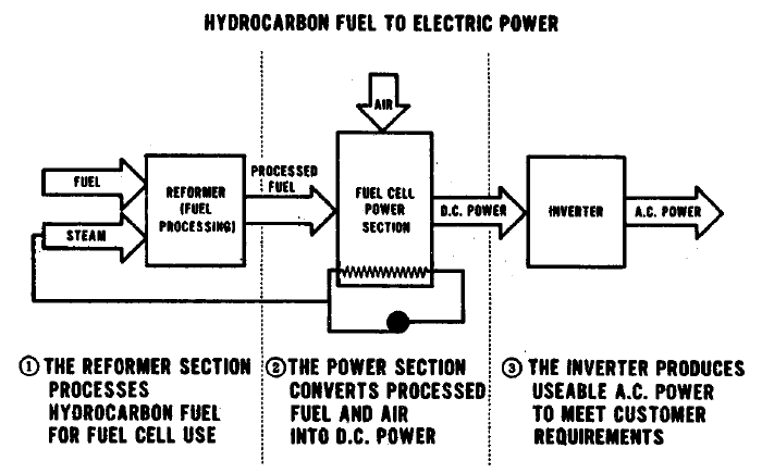
The uses to which fuel cells may most profitably be applied are electric power generation and transportation. Most of the nonelectrical energy in the industrial sector, and nearly all in the commercial and residential sector is used for heating. Conversion of fuel to heat usually proceeds with high efficiency, so relatively little application of fuel cells in these sectors is seen. Because the fuel cells convert chemical energy directly to electrical energy, electrical power generation is probably their most natural application. While the output of each cell is low voltage dc power, cells may be connected in various series and parallel arrangements to give whatever voltage is desired, and large highly efficient inverters are available for conversion to ac.
A fuel cell system, unlike a heat engine, need not be big to be efficient. This characteristic, taken together with two others, low emissions and capability of operation on a variety of fuels, allows fuel cell systems to be operated almost anywhere. A small community power company can operate a power plant on the optimum fuel available locally with nearly the same efficiency achieved by a large central power station. A large metropolitan utility can disperse a number of generators throughout its area and match capacity to local demand, substantially reducing the expense and other problems associated with transmission and distribution of electricity.
In the transportation industry, the same virtues of efficiency and low pollution make the fuel cell attractive. Fuel cell systems of adequate performance to propel railroad trains, barges, and ships can probably be built with existing technology, at least, as far as cells themselves are concerned. All of the basic technology is available, the Fuel Cell power plant would be very smooth and quiet, virtually pollution-free, and could operate on conventional fuel –This book will tell you how!
 |
 |
|
 |
FUEL CELL OPERATION
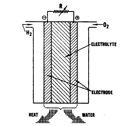
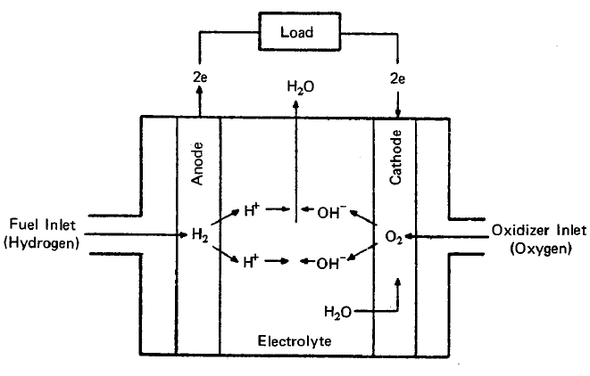
The essential features of a fuel cell (1)(2)(4)(5) are shown in Figure 2.1. The main components are a fuel electrode (anode), an oxidant or air electrode (cathode) and an electrolyte. In a typical application, the reactants are fed through the electrodes which are porous and are brought into contact with the electrolyte. Reactions take place which produce voltages at the electrodes. When an external load is connected, electrons are conducted through the load and perform useful work; whereas in the electrolyte, ions travel from one electrode to the other, completing the electrical circuit. Fuel cells continue to operate as long as the current flows through the load, as long as fuel and oxidant are supplied to the cell, and as long as structural and chemical integrity is maintained.
The principal reactions which occur in a hydrogen-oxygen fuel cell (2)(4) are shown in Figure 2.1. In this fuel cell hydrogen is fed through the anode where it reacts in the presence of a catalyst forming electrons and H+ ions, the latter passing into the electrolyte. At the other side of the fuel cell, the oxygen which is fed through the cathode acquires electrons and reacts with water from the electrolyte to form hydroxyl ions (OW). In this type of fuel cell, a solution of potassium hydroxide (KOH) is often used as the electrolyte. The Fl+ and the OH- ions are in equilibrium with water in the electrolyte. Electrons released at the hydrogen electrode pass through the external load circuit and are captured at the oxygen electrode. The electrical output from an individual cell is typically a direct current of 100 to 200 mA/cm2 at a voltage of about 1 volt (depending upon the reactants employed) (3)(11)(12). These cells can be connected in series and/or parallel to obtain a unit which will provide the appropriate voltage and current.
|
|
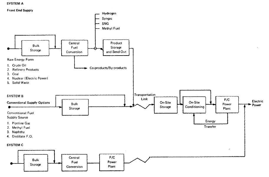 |
FIGURE 3.1: FUEL CELL POWER PLANT FUEL SUPPLY SYSTEMS
MODULAR APPROACH
In developing fuel cell fuel supply systems, three basic approaches were considered. The first, referred to as System A, consists of converting raw fuel at a central conversion facility and distributing a clean product fuel to dispersed fuel cell power plants.. ,,System B involves the delivery of purchased hydrocarbon feedstocks directly to the dispersed power plants where they are converted on-site to fuel cell .grade fuels. System C involves integrating a central station fuel cell with a central coal gasifier to eliminate fuel transportation costs, to fully integrate-all,necessary conversion in a single plant, and to take advantage of the economics'ofrscale of a large base load system. The general system schematic for these three options is shown in Figure 3.1.
|
|
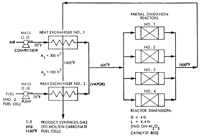 |
FIGURE 3.6: PROCESS FLOW DIAGRAM FOR A PARTIAL OXICATION PLANT - 26 MW
A process flow diagram for a
catalytic partial oxidation fuel conditioner using distillate oil is shown
in Figure 3.6 for synthesis gas production. No water is used in the process
and carbon monoxide is not shift reacted to hydrogen, since the product gas
is fed to a molten carbonate cell
|
|
 |
|
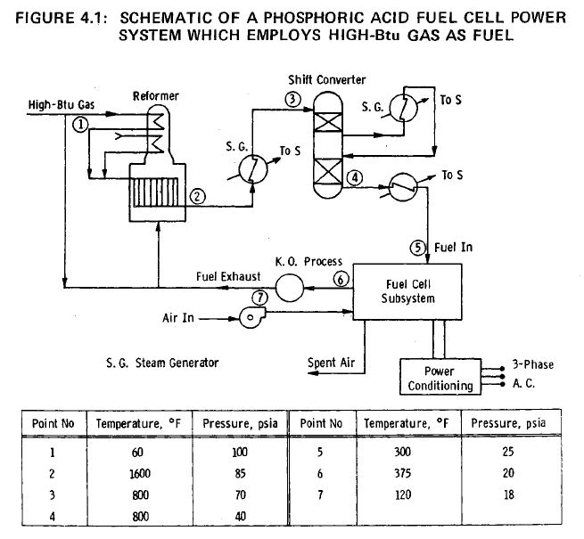
A schematic of the complete power system is shown in Figure 4.1. High-Btu gas from a 0.689 MPa (100 psi) abs line is assumed to be available, and is fed after preheating to a steam-methane reformer operating at a pressure of 0.689 MPa (100 psi) abs and a temperature of 1144°K (1600°F). The reformer effluent, consisting mainly of carbon monoxide, hydrogen, carbon dioxide and steam, is cooled and fed to a shift converter operating at 0.483 MPa (70 psi) abs and 700°K (800°F). The shift converter is operated at as low a temperature as possible in order to minimize the carbon monoxide concentration in the exit gas. The hydrogen-rich fuel gas is further cooled to approximately 422°K (375°F) and is fed to the ten fuel cell modules. Air is supplied to the modules by means of blowers, as shown in Figure 4.1.
Steam, required for the
steam reformation of methane (the principal constituent of
high-Btu gas) is raised in the cooling of the fuel gas between
the reformer and the shift converter, in the shift converter,
and between the shift converter and fuel cell subsystem. The
water required for the steam generators is reclaimed from the
fuel-gas exhaust by the knock-out process shown in Figure 4.1.
The water-vapor depleted exhaust gases, containing approximately
10% of the hydrogen fed to the fuel cell modules, and the
unused carbon monoxide, is mixed with a portion of the incoming
high-Btu gas, and the mixture is burned to supply the heat
required to cover the endothermic processes in the reformer.
Further details of the fuel processing subsystem are provided
in Appendix 1
|
|
 |
FIGURE 6.5: ENERGY EFFICIENCY - COST OF ELECTRICITY MAP FOR VARIOUS TYPES OF FUEL CELL POWER PLANTS
OVERALL COMPARISON
With the aid of Figure 6.5 an overall comparison of the results of the fuel cell portion of the parametric study can be made. The G.E. low temperature fuel cell system points are divided into two groups to indicate the significant effect of hydrogen fuel. Likewise, the Westinghouse high temperature points are
divided into two groups to indicate the significant effect of using a steam bottoming cycle and/or integration with the gasifier. The general conclusions that can be drawn from inspection of Figure 6.5 are as follows:
(1) With low temperature fuel cell power systems the use of hydrogen fuel in place of H Btu gas improves efficiency and lowers the cost of electricity (COE).
(2) The Westinghouse estimates of low temperature fuel cell efficiencies (with no hydrogen fuel cases) were all higher than the G.E. overall efficiency estimates for H Btu/air. The Westinghouse estimates of COE for these same cases were either higher or lower than those of G.E.
(3) The results indicate that, in general, high temperature fuel cell systems are more efficient than low temperature fuel cell systems.
(4) Using a steam bottoming cycle and/or integration with the gasifier results in the highest efficiencies obtained with a high temperature fuel cell.
(5) The estimates by Westinghouse of the high temperature fuel cell efficiencies for systems with a steam bottoming cycle are significantly higher than a E.'s estimates.
Additional conclusions based on a closer examination of the results are discussed in the following section. In addition, the present general conclusions are more precisely stated and discussed. Finally, it is important to state that optimization was not a goal of Phase 1 of ECAS. Optimization could result in points with reduced COE
|
|