|
Hydrogen Technology For Energy
|
 |
|
Hydrogen is a most promising future medium for energy transmission and storage. It may be extracted from fossil fuels, from water or both simultaneously. While fossil fuel supplies must be regarded as a limited resource, water may be considered inexhaustible.
In addition to the raw material sources consumed in hydrogen production, energy sources must be used to extract hydrogen from fossil supplies or from water. This energy can be obtained directly from fossil fuels but primary energy sources including nuclear, solar, wind, fossil, geothermal, or ocean temperature gradients must be used to obtain hydrogen from water.
If hydrogen is to become a widely used energy carrier, it must be produced economically and efficiently on a large scale for a long time period. Therefore hydrogen production must be linked to those primary energy sources which are currently available, as well as to those which might be available in the future.
Hydrogen can be produced by current primary energy sources (for example, gas, oil, coal, fission) as well as by those energy sources which might be available in the future (i.e., fusion). Two important routes couple the several primary sources to hydrogen, thermochemical decomposition and electrolysis. Several primary sources could utilize either path (for example, nuclear or solar), while other sources only seem practical when coupled to one of these paths (for example, wind-electrolysis, geothermal-electrolysis).
An important characteristic of the future energy supply of the United States is that it will probably be based upon many primary sources. This trend is the result of the heavy demand on the limited domestic energy supplies. Economic and environmental constraints may cause energy to be extracted from many sources so that costs can be held down and the resulting pollutants (including reject heat) can be disposed of in many reservoirs. This book will guide you through Hydrogen Technology subject areas starting with the ways in which primary energy can be converted into hydrogen in ways that minimize economic and environmental costs.
|
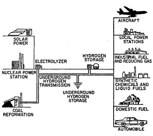 |
FIGURE 1.3: THE HYDROGEN ENERGY CONVERSION SYSTEM
If hydrogen were adopted as the main general-purpose synthetic fuel, the energy conversion system would probably have a configuration as illustrated in Figure 1.3 (29)(30). As the system grows, hydrogen would probably be produced by a variety of primary energy sources, initially by coal gasification and off-peak power from nuclear steam-electric generating plants, supplemented later by solar, geothermal, and fusion steam-electric generating plants. Perhaps in the more distant future, methods can be developed to produce hydrogen more directly from nuclear and solar heat by thermochemical reactions.
|
|
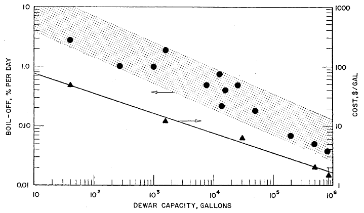 |
FIGURE 3.4: BOIL-OFF LOSSES AND CAPITAL COSTS FOR LIQUID HYDROGEN STORAGE DEWARS
Boil-off loss data and some cost data are plotted in Figure 3.4 versus tank capacity. These data indicate a rough trend for boil-off losses versus capacity; however, it is not surprising that the correlation is poor, since the vessel shape and type of insulation used varied widely. Detailed specifications for the various insulations used are not readily available so no attempt has been made to correlate subsets of the total body of data for specific types of insulation.
|
 |
Its superconducting transition temperature (Tc) is about 18K. Newer materials such as alloys of Nb, Al, and Ge, have ; values higher than 20K. To maintain superconducting properties in materials such as alloys of Nb, Al, and Ge,, coolants such as liquid helium (4K), slush hydrogen (14K), or a combination of the two must be used. There are economic advantages to using slush hydrogen, but the possible containment problem must again be examined.
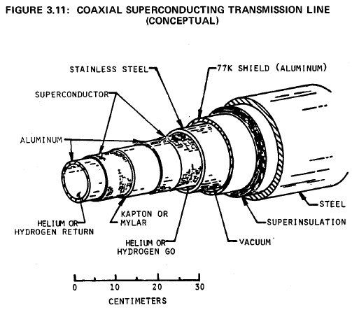
A drawing of one of several prototype designs is shown in Figure 3.11 (64). It is proposed that this design be used in a DC transmission line one kilometer long, with a power rating of five gigawatts. The superconducting material is plated onto the outer surfaces of two concentric aluminum tubes. Helium or slush hydrogen refrigerant will flow through the system at a pressure near one atmosphere. Surrounding the conductors and coolant are a stainless steel containment tube, a vacuum jacket, radiation shield, insulation and a structural steel case.
|
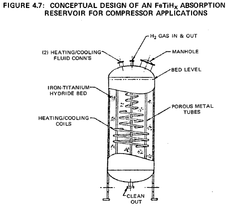 |
A simple design for a compressor would be a shell and tube heat exchanger, with the FeTiHx compound on the shell side and a coolant/heating bundle penetrating the granular bed. Hydrogen could be injected and removed from the bed through small diameter porous metal tubes dispersed in the bed and connected to a common header. Cooling would be by ambient temperature cooling water circulating through the tubes.
During H2 desorption hot water (or steam) from the low temperature heat source would circulate through the tubes. Figure 4.7 shows a conceptable design of an iron-titanium hydride compressor.
The pressure composition isotherms of the FeTiHx system generally exhibit some hysteresis.
This results in some inefficiency in the cycle; the reaction is not
completely reversible since the equilibrium charging pressure is slightly
higher than the equilibrium discharge pressure. However, it is shown later
that with available material this inefficiency is tolerable
|
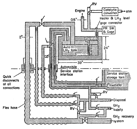 |
FIGURE 5.14: AUTOMOBILE DEWAR SYSTEM
A sketch of a car Dewar is given in Figure 5.14. The vehicle LH2 Dewar may be refilled or replaced at a service station whenever resupply is required. The number of connections for refilling the Dewar could be as many as five (electrical, LH2 supply, tank vent, vent line purge, and supply line purge) or as few as two (electrical and gas supply to engine) for replaceable Dewars. The number of connections should be minimized and reliable quick-disconnect type fittings should be developed to expedite refueling.
|
|
|
|