|
Hydraulic Motors
|
 |
|
Hydraulic Motors was written with students of engineering in mind. To ensure a clear and sound foundation in the mechanics of water power this book provides the reader with illustrations of the mechanisms and algebraic treatments, along with more than enough descriptive content to make it extremely practical for its purpose.
In Hydraulic Motors attention is given to centrifugal pumps and other allied appliances; it contains diagrams of friction-heads in pipes and those for determining Kutter's coefficients for open channels (found in the Appendix) and identifies special problems, closely connected with the subject of water-power, involving pipes, weirs, and open channels; the experiments of Joukovsky on water-hammer are also presented and the theory of this phenomenon is developed. Hydraulic Motors will prove incredibly useful to practicing engineers and enlightening for students, experimenters and energy science enthusiasts.
|
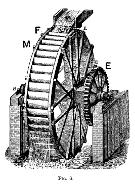 |
Fig. 6 represents a wooden Overshot Water-wheel of this class, revolving in a vertical plane on an axle in firm bearings. As seen from the figure it consists of two ring-shaped shroudings, or crowns, connected with the axle by radial arms, and a number of floats or buckets inserted between the crowns and forming, with them and a cylindrical boarding concentric with the axle, a series of cells. The water is supplied from a sluice or pen-trough near the top of the wheel, and is regulated by a gate, falling in a sheet, or jet, into the third or fourth bucket from the summit. These wheels have been constructed for falls of from 4 to 70 ft., sometimes receiving as much as Q-50 cub. ft. of water per second; and of from 3 to 50 or more horse-power. With high falls and a large supply of water it is better to use two or more small wheels rather than a single large one, whose necessarily great. weight would be a disadvantage. The fall is measured from the surface in the supply channel, or pen-trough, to that of the tail-water. To lose the least head possible the wheel should hang just tangent to the tail-water; or, if the level of the latter is variable, high enough to avoid contact. In Fig. 6 H is the axle, B and C its gudgeons; DMF, D'M'F', the crowns, or shroudings, made in 8 to 16 segments and from 3 to 5 in. thick, and fastened to each other by cross tie-bolts which also pass through the arms. The cog-wheel E serves to transmit the power to the machinery. More elaborate wheels of this class have been built of iron, with sheet-iron floats. |
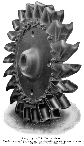 |
As can be seen in Figs. 30, 31, and 32, the two lobes of the Pelton bucket are rectangular in form, while those of the Doble wheel, called " ellipsoidal " by the makers, are oval, with notches cut out at the point of first impingement of the jet. In the "Cascade" wheel the "lobes," or half-buckets, are set "staggering," or "breaking joint," on the two sides, and near the rim, of a thin circular disc, whose sharp edge serves the same purpose as a dividing ridge to split the jet. |
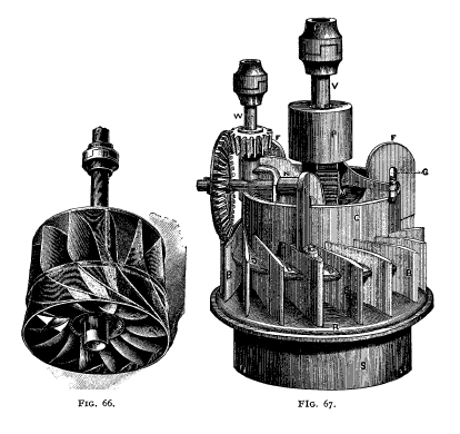 |
American Turbines. Fig. 66 shows the "runner," or turbine itself, which has a curved upper crown; the place of a lower crown being taken by a vertical cylindrical band In Fig. 67 is seen an outside view of the wheel-case, the guide-vanes, B, are fixed upon the ring R. S is the short discharge-tube, intended to dip a few inches below the surface of the tail-water. The gate is a vertical cylinder, seen at C, and in this make of turbine is furnished with a number of horizontal extension pieces, such as D. |
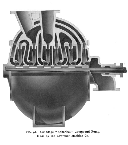 |
In Fig. 91 is shown a section (through axis of shaft) of a 6-in., six-stage, "spherical," "compound pump" constructed, by the arrangement of the impellers in pairs and by the position of the intervening guide-passages, so that the resultant end thrust is zero. |
|
|
|