CHAPTER 1: HYDROGEN-ITS USES-DISCOVERY, AND OCCURRENCE IN NATURE
CHAPTER 2: THE CHEMICAL PROPERTIES OF HYDROGEN
By means of adiabatic compression, the temperature of ignition of different mixtures of hydrogen and oxygen was determined, with results which may be seen in Fig. 1. From a study of this curve it will be noticed that the most easily ignited mixture is not one in which the proportion of hydrogen to oxygen is as two to one, as might perhaps be expected, but when the ratio is one volume of hydrogen to four of oxygen.
 |
While referring to the production of chemical union between hydrogen and chlorine brought about by the influence of light, attention may be drawn to what is known as the " Draper Effect," which is best demonstrated in Fig. 2. The mixed gases, in the ratio of one volume of hydrogen to one of chlorine, are contained in a flat glass bulb A, called the insolation vessel. The lower part of the insolation vessel usually contains some water saturated with the ,two gases. The capillary tube BC contains a thread of liquid ac, to serve as an index. Under the influence of a flash of light the thread of liquid ac is pushed outwards, to return immediately to its original position. Thus, a travels to b, and immediately returns to a. With every flash of light the same phenomenon takes place.
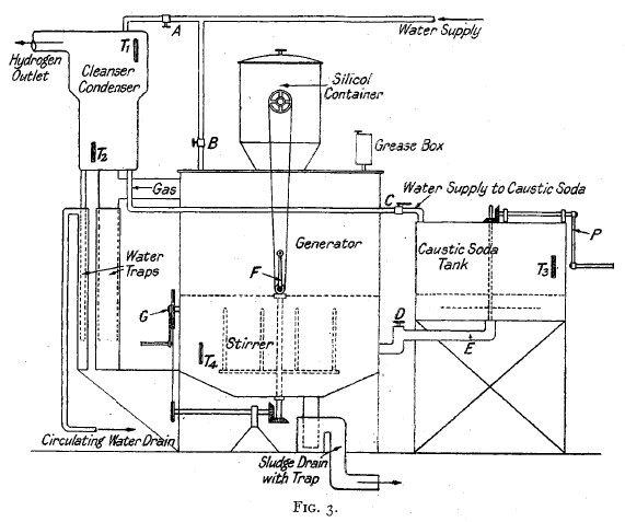 |
Description of Silicol Plant—The essentials of a silicol plant are shown in the diagram (Fig. 3). The requisite quantity of caustic soda is placed in the tank on the right and the necessary water added to it to make a 25 per cent. solution. To assist solution there is a stirrer in this tank, which, in small plants, is hand-operated and in large ones power-operated. When the whole of the caustic soda has gone into solution, which it readily does as a result of the heat of solution and the stirring, the valve D is opened, allowing the whole of the soda solution to run via the pipe E into the generator. When the solution has run from the caustic soda tank into the generator the valve D is closed, then the necessary quantity of ferro-silicon is placed in the hopper on the top of the generator and the lid of the hopper closed, making a gas-tight joint. In small plants a little mineral grease is added to the generator, via the grease box. |
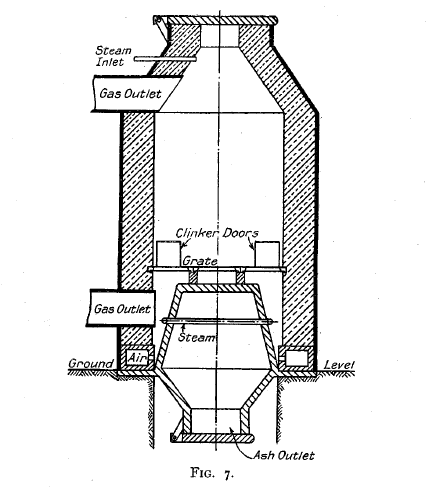 |
Fig. 7 shows a modern water gas producer, which is self-explanatory ; the fuel charging is done after every third steam blast, and the depth of the fuel kept correct by means of a gauge rod, dropped through the lid at the top of the generator. The same alternation in the direction of the steam blast is maintained, while during the air blast the products of combustion escape through the lid at the top of the generator, which is open during this stage. |
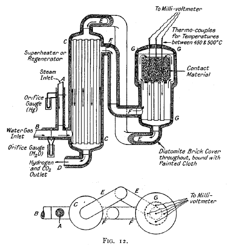 |
In (Fig. 12) steam enters by
the pipe A and mixes with blue water gas entering by the pipe.
B, the speed of flow of each being indicated on separate gauges
as shown. The mixture of steam and gas passes through the
regenerator or superheater C and flows, as indicated by the arrows, over refractory tubes, through which the hot products of the reaction are flowing in the reverse direction. The heated mixed gases flow via the pipe F into the generator and, increasing in temperature, pass through the catalytic material, where reaction takes place with the evolution of heat. They then flow as indicated by the arrows back through the regenerator, parting with their heat to the incoming mixture of blue water gas and steam. |
CHAPTER 4: THE MANUFACTURE OF HYDROGEN: CHEMICO-PHYSICAL METHODS
 |
In the Linde-Frank-Caro process the blue water gas, is compressed' to 20 atmospheres, and under pressure it is passed through water, which removes practically the whole of the carbon dioxide and sulphuretted hydrogen. It is then passed through tubes containing caustic soda, which removes the remaining traces of carbon dioxide, sulphuretted hydrogen, and water...
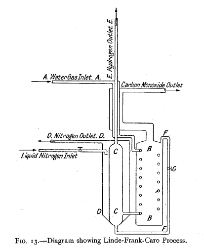
In Fig. 13 the purified water gas passes down the tube A, through coils in the vessel B, which is filled with liquid carbon monoxide boiling at atmospheric pressure — 190° C.). Now, since the water gas is under pressure and is passing through coils cooled to its temperature of liquefaction at atmospheric pressure, the bulk of it liquefies (theoretically more gas should be liquefied in the tubes than is evaporated outside them). The gas, containing a considerable amount of liquid saturated with hydrogen, passes into the vessel C, which is surrounded by liquid nitrogen boiling under reduced pressure giving a temperature of — 205° C. |
CHAPTER 5: THE MANUFACTURE OF HYDROGEN. PHYSICAL METHODS
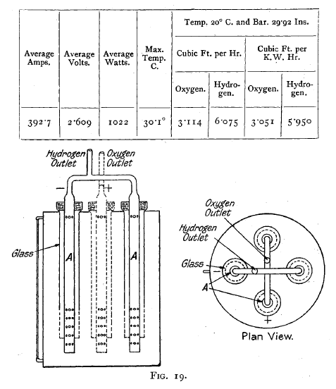 |
The Non-Conducting, Non-Porous Partition Type.— This cell, which is illustrated by the diagram (Fig. 19), consists of a metal tube A, which forms the electrode and gas outlet, and which is made of lead where an acid electrolyte is used, and of iron where an alkaline one is employed. This metal electrode is surrounded by a glass or porcelain tube perforated at the bottom.
There are four of these electrodes per cell, which are arranged as indicated in the diagram. When the current is switched on the gases are liberated on the electrodes within the glass tube ; consequently no mixing of the liberated gases can take place.
|
APPENDIX: PHYSICAL CONSTANTS
 |
|
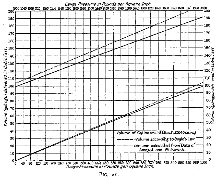
The relationship between volume and pressure when the latter is great has been investigated by Amagat and Witkowski, whose results are incorporated in the graph (Fig. 21), which shows the relationship between the theoretical volume of hydrogen which should be obtained on expansion to atmospheric pressure and that which is obtained from a standard hydrogen cylinder. From this it is seen that, on expansion from 2000 lb. per square inch- to atmospheric pressure, 9.2 per cent. less volume of hydrogen is obtained than is indicated by theory. |
|